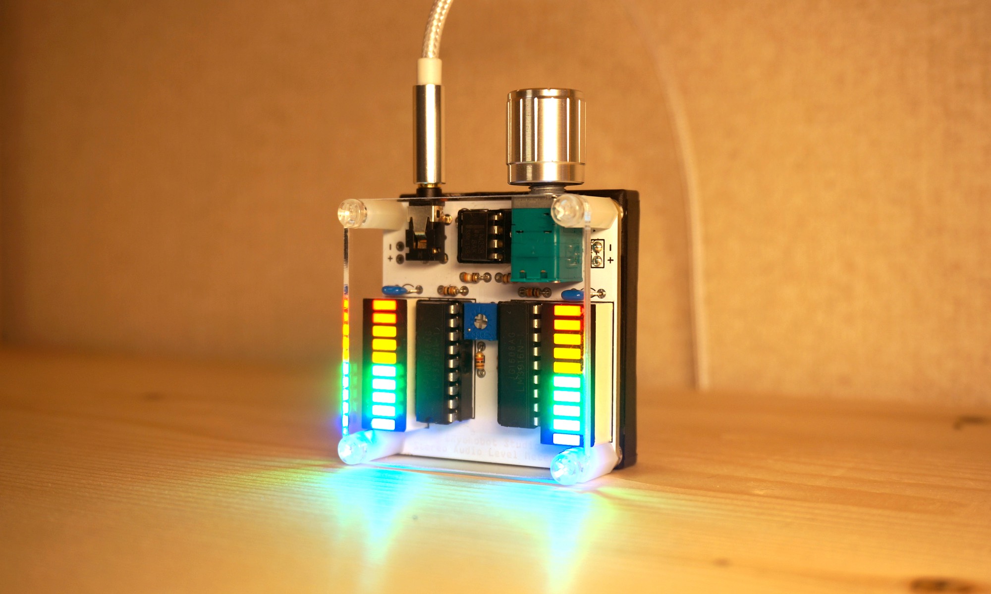
Thank you for purchasing / considering the Stereo Audio Level Meter V2.
This page is the support page of Stereo Audio Level Meter V2.
How to use and how to assemble is posted.
日本語ページはこちら!(Japanese page is here)
Promotion Movie
# How To Use
① Install four AAA batteries
② Connect the sound source and level meter with a 3.5 mm audio cable
③ Play the sound source
④ Turn the power on by turning the knob of the level meter to the right
⑤ Turn the knob on the level meter to adjust the sensitivity
If the left and right balance (sensitivity) is misaligned
· Turn the semi-fixed resistor in the center of the board with a Phillips screwdriver to adjust the balance between the left and right.
Upgrade item from the first level meter to V2
· Grade up from plastic knob to metal knob
· Added left / right balance adjustment function
· Designed with awareness of symmetrical arrangement of parts
· Electronic Substrate · Acrylic cover modified to round design
· Improve substrate silk for easier understanding
· Add color variation
· Improved holes in boards where audio jacks were tightened
· Substantial change of board pattern to correspond to multicolor LED
· Standard attachment of acrylic cover and mounting plunge & spacer
# Consignment Sale
初代ステレオオーディオレベルメータキットをスイッチサイエンスにて委託していました。
https://www.switch-science.com/catalog/1965/
ステレオオーディオレベルメータV2も現在委託準備中です!
Kit Parts List
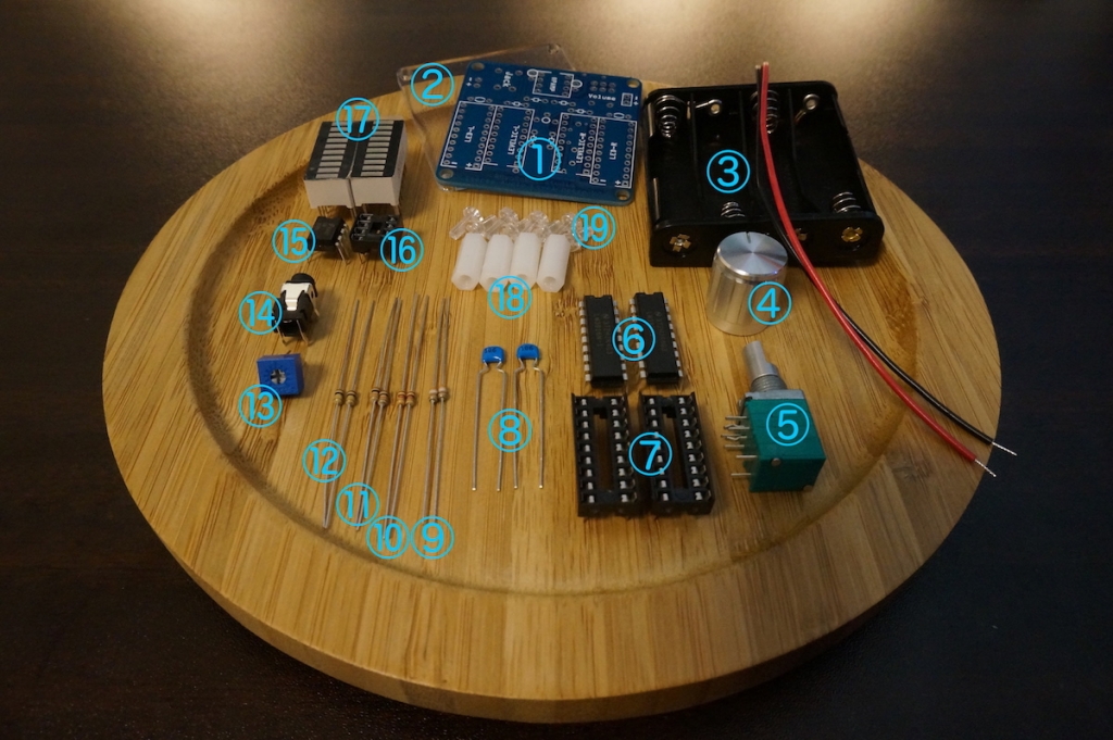
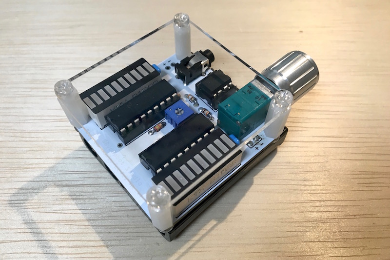
① Stereo Audio Level Meter V 2 Electronic Substrate
② Acrylic cover
③ 4 AAA batteries box
④ Volume knob
⑤ Volume with switch
⑥ Level meter IC (2 pieces)
⑦ 18 pin IC socket (2 pieces)
⑧ 10 uF ceramic capacitor (2 pieces)
⑨ 390 Ω resistor (color code: orange white brown gold) (2 pieces)
⑩ 1 kΩ resistor (color code: brown black red gold) (2 pieces)
⑪ 10 kΩ resistor (color code: brown black orange gold) (2 pieces)
⑫ 100 kΩ resistor (color code: brown black yellow gold) (2 pieces)
⑬ 2 kΩ semi-fixed resistance
⑭ Stereo jack
⑮ OPAMP
⑯ 8-pin IC socket
⑰ Bar LED (2 pieces)
⑱ Screw spacer (4 pieces)
⑲ Plastic bolt (8 pieces)
37 points in total
Other necessary items
· Four AAA batteries
· 3.5 mm audio cable
How to Assemble
Required Tools
・Nipper
・ Wire stripper
・Soldering iron
・ Soldering iron stand
・solder
・ Glue gun or adhesive
・Phillips screwdriver (smaller)
To Prepare As Necessary
· Solder sucking device
· Radio pliers
· Flathead screwdriver (smaller)
Attention Before Assembly!
· Be careful not to injure yourself or burn yourself because it uses high temperature tools.
· Please be careful not to enter the eyes as fragments scatter as when cutting the wire of the part.
· When working around where there are people, please also pay attention to people around you to work.
· If metal pieces such as parts wires remain on the board, it may cause a short circuit, which is dangerous. Please also work on the solder bridge.
· Be careful when checking the operation after completion. If the IC or battery is generating heat, etc. after power is turned on, the IC’s orientation error or short circuit may be considered, immediately turn off the power supply Please give me.
( Note: This assembly explanation is written for those who have done soldering to a certain extent. If you are a soldering beginner, practice soldering and perform assembly work after getting used to a certain extent.)
1. Check Parts
Check parts with reference to parts list.
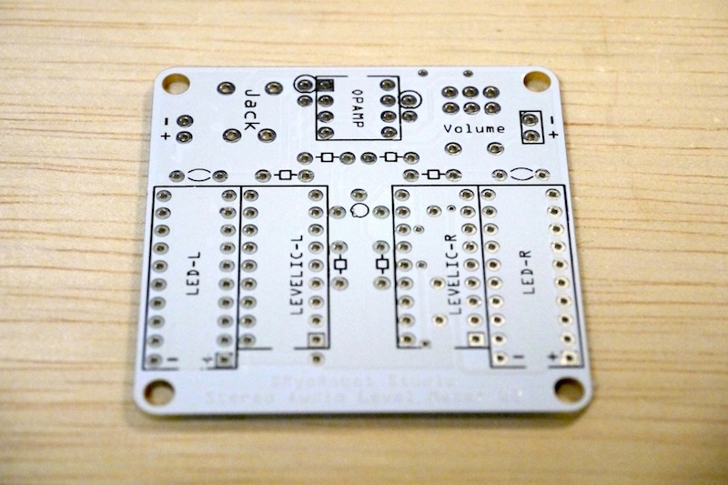
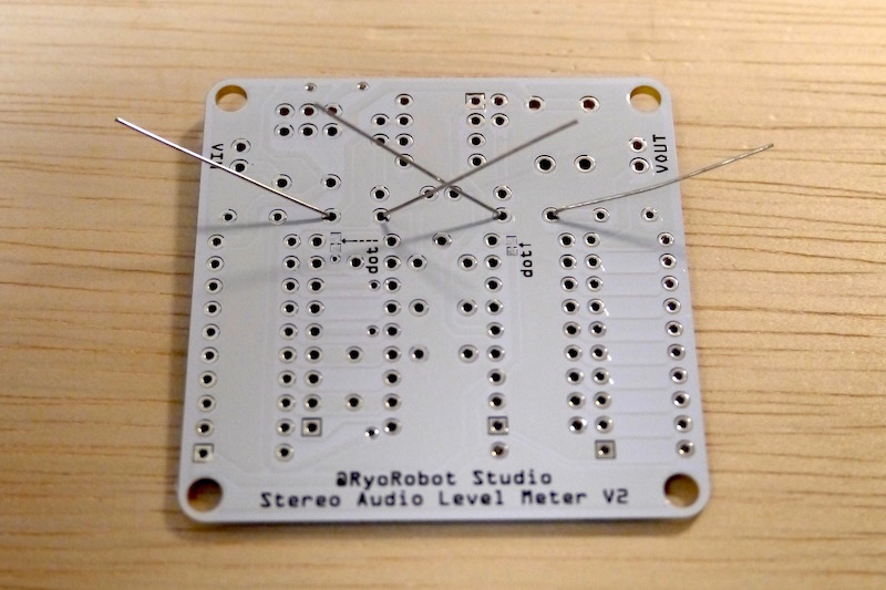
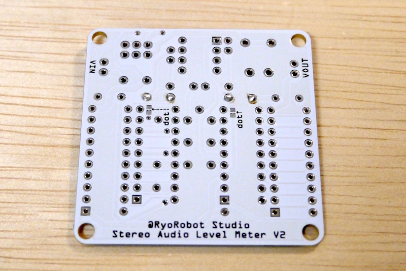
2. Confirm board
We will install parts on the side where many rectangular frames (silks) are written.
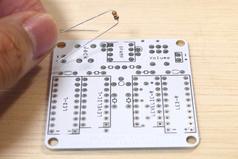
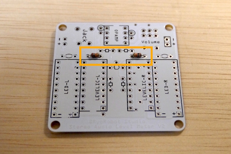
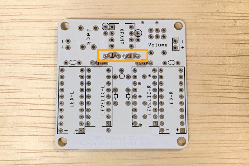
3.Installing a 10 kΩ resistor
Fold the 10 kΩ (color code: brown black orange gold) resistor lead in a U shape and insert it in the place of the figure and solder it.
Cut the remaining lead with a nipper.
※ There is no polarity in the resistor, so it is OK to install in either direction.
4. Installation of 390Ω resistor
Fold the 390Ω (color code: orange white brown gold) resistor lead in a U shape and insert it in the place of the figure and solder it.
Cut the remaining lead with a nipper.
5. Installation of 1kΩ resistor
Fold the 1kΩ (color code: brown black red gold) resistor lead in a U shape and insert it in the place of the figure and solder it.
Cut the remaining lead with a nipper.
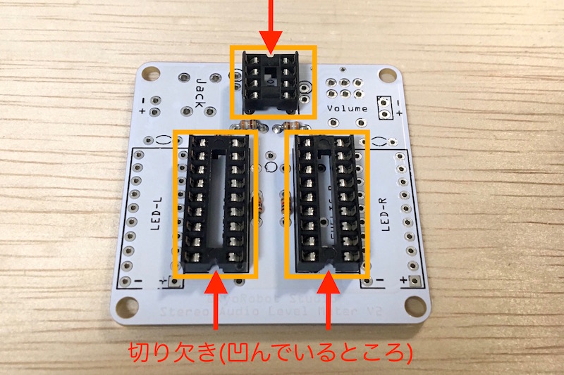
6. Installation of IC socket
Solder the 18-pin IC socket for the level meter IC with the notch pointing downward.
Solder the 8-pin IC socket for the operational amplifier with the notch facing upward.
※Since it is a part with many leads, if you can not insert it into the board successfully, make sure that all the leads are straight and insert the lead bent readily while keeping it straight.
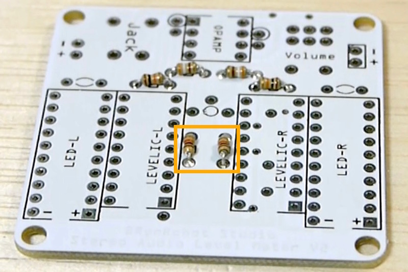
7. Installation of 100kΩ resistor
Fold the 100kΩ (color code: brown black yellow gold) resistor lead in a V shape and insert it in the place of the figure and solder it.
Cut the remaining lead with a nipper.
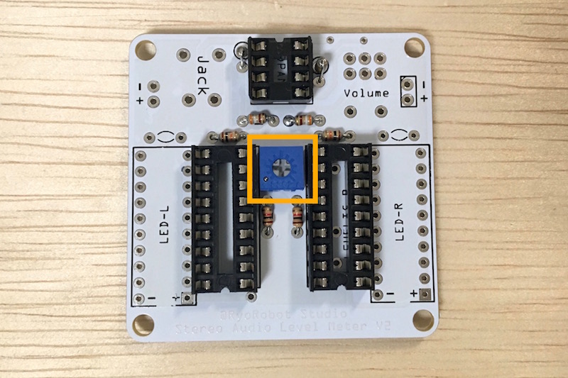
8. Installation of semi-fixed resistor
Insert a semi-fixed resistor in the place of figure on the board and solder it.
Cut the remaining lead with a nipper.
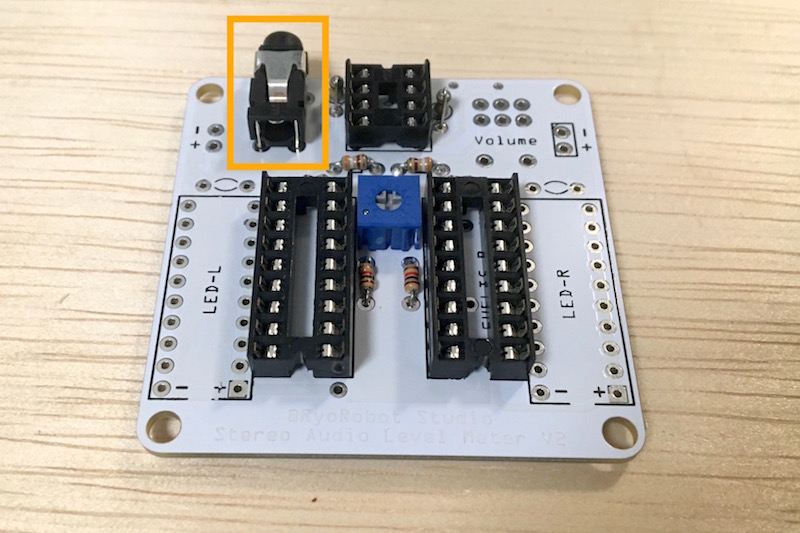
9. Installing a 3.5 mm audio jack
Insert a 3.5 mm audio jack into the place written “Jack” on board and solder it.
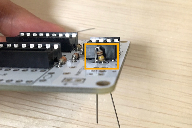
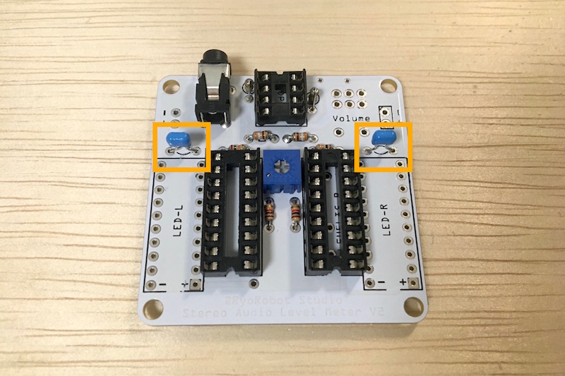
10. Mounting multilayer ceramic capacitor
Solder the 10 uF multilayer ceramic capacitor to the place shown in the figure.
※ Multilayer ceramic capacitor has no polarity, so it is OK to install it in either direction.
Cut the remaining lead with a nipper.
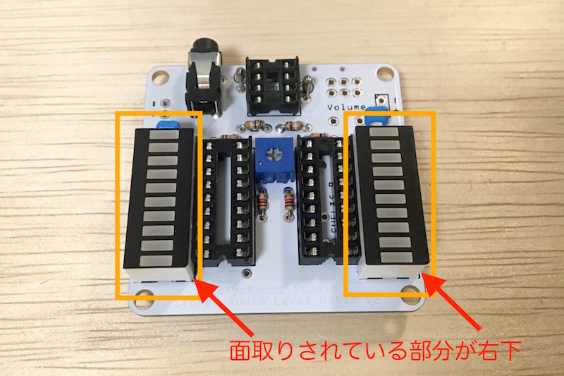
11. Installing the Bar LED
(Caution point!) One of the four sides of the side of the bar LED has a corner on it. (It is easy to understand when touching with your finger.) Insert it like the figure so that this side comes to the lower right.
Then, solder it.
※Since it is a part with many leads, if you can not insert it into the board successfully, make sure that all the leads are straight and insert the lead bent readily while keeping it straight.
Cut the remaining lead with a nipper.
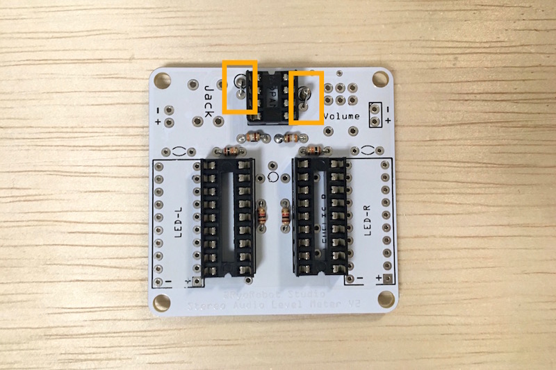
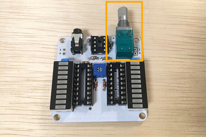
12. Installing a volume with switch
Attach the volume with switch to the place written “Volume”.
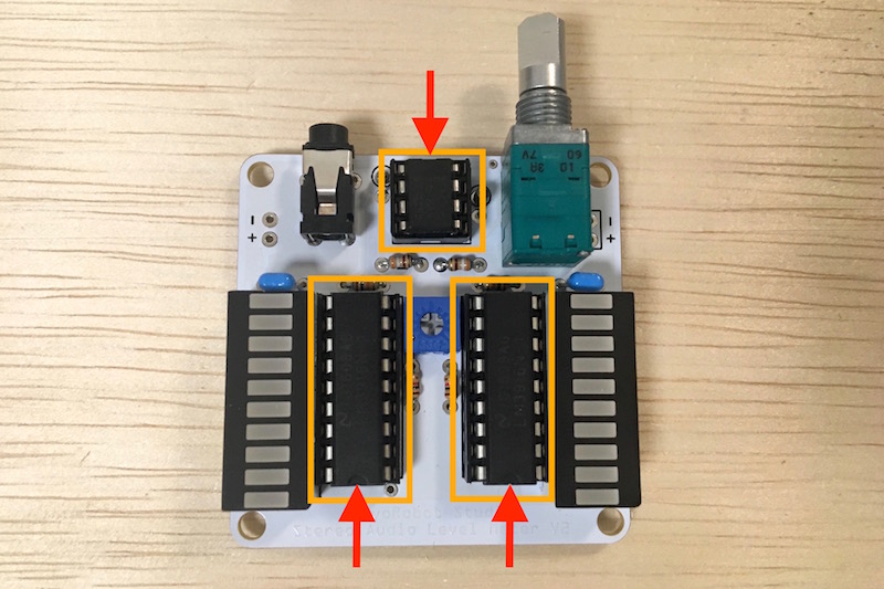
13. Installing IC
· Install the level meter IC and op amp.
· New IC’s lead is open and can not be inserted into the IC socket as it is, so make the pin straight.
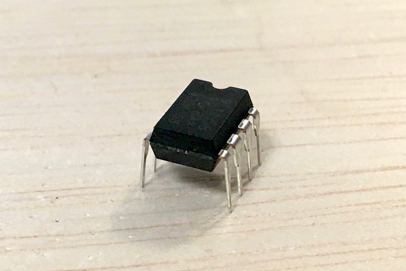
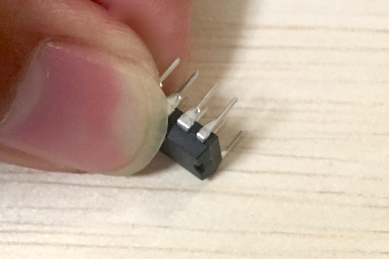
· Like the 18-pin IC socket, the level meter IC faces the notch downwards, and the OPAMP installs with the notch facing up like the 8 pin IC socket. (Even if you misdirect the IC socket, it moves if the direction of the IC is not wrong)
14. Attach the lead wire of the battery box
Cut the red and black lead wires to just right length and peel off the coating a little with a wire stripper or nipper.
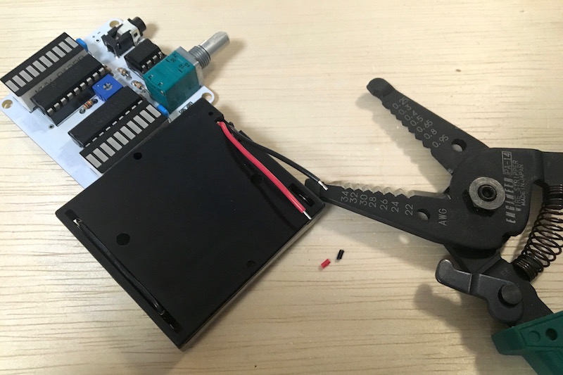
(Caution point!) Please cut off the part where the sharp leads of the sharp parts come out from the board with the nipper at the part which becomes the path of the line of the battery box. If you do not do this work there is a danger that the lead of the part sticks to the line of the battery box and short-circuits.
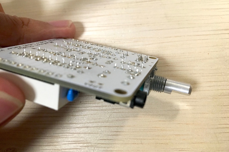
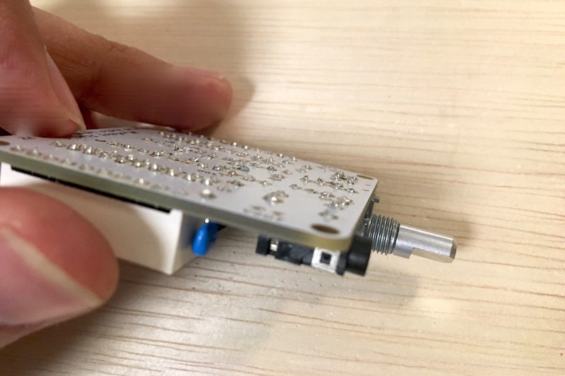
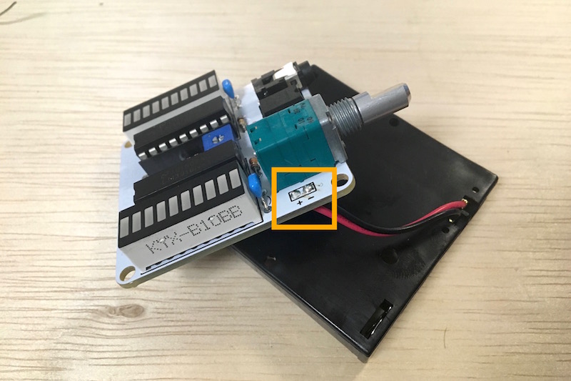
Solder the red wire to the + side of the VIN terminal on the right side of the board and the black lead wire to the – side.
(Caution point!) If you mistake + -, it may cause overheating, fire, or malfunction.
Cut out the wires (stripped portions) remaining on the board with the nipper.
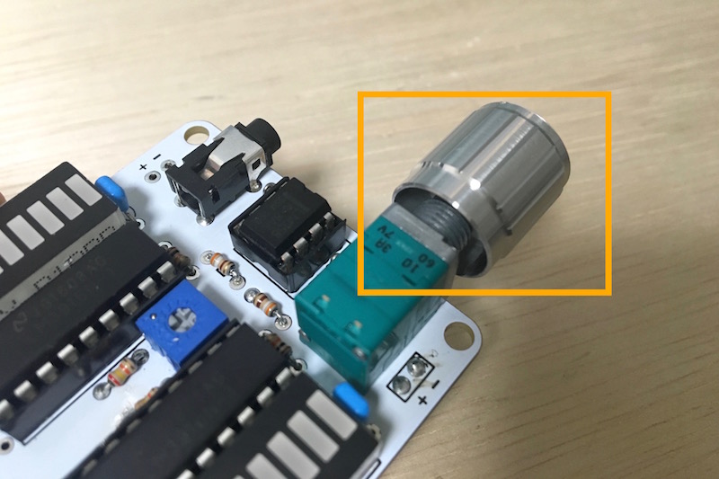
15. Attaching the volume knob
Insert the volume knob (strongly).
16. Attaching the acrylic cover
・Peel off the protective film of the acrylic cover.
・Attach the board and acrylic cover with a spacer and plastic bolt with a Phillips screwdriver.
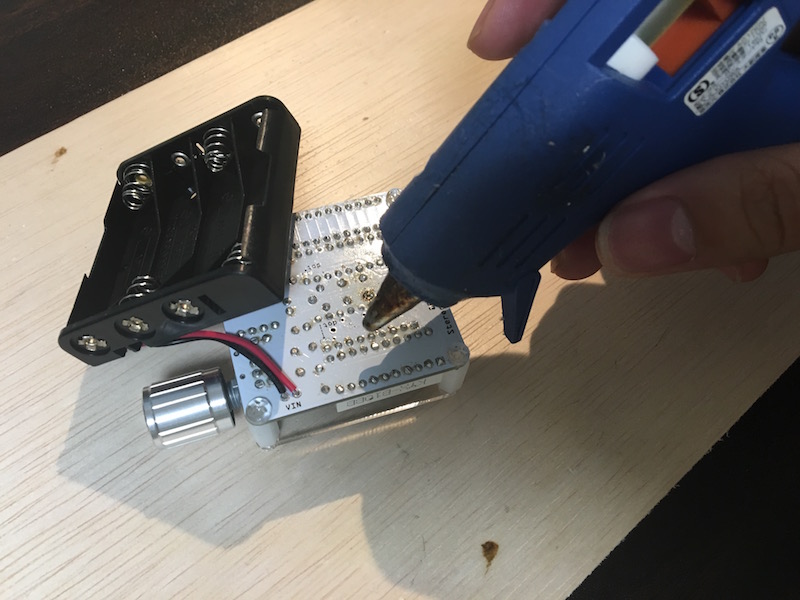
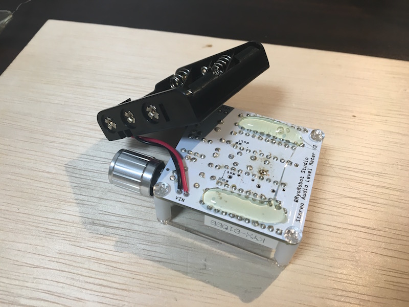
17. Bonding of battery box
・Use glue gun to bond the battery box and board.
・ Besides glue gun, you can use adhesive or thick double-sided tape.
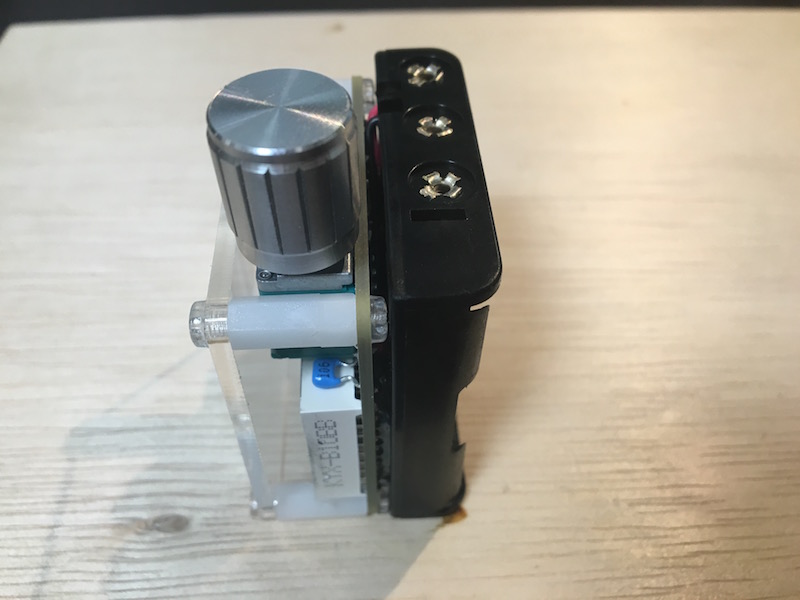
18. Completion!
Contacting
If you need help with this kit,
Mail: ryorobot@gmail.com
Thank you.